Before it i'm so sory about my bad english, there is translating from my dictate in indonesian to english
Update 26 August 2013
Update 26 August 2013
Spur gears
In the manufacture
of gears, a few dimensions of the gears to be made must be understood
first through working drawings. For the manufacture of gears Spur there
is to know such as the number of teeth (z), the size of the module (m),
so the number of tooth and module size can be determined diameter heads
(Dk), a high tooth (h) and the width of a few tooth (Wk) which obtained
through calculation. Diameter of heads is needed when turning diameter,
height and width of a few tooth tooth is necessary when the tooth
forming in the milling machine. Here is the sequence of the process of
making Spur gears.
1. Prepare working drawings.
Working
drawings are very important in the manufacture of a product in this
gear, because without a picture of the operator is not able to work on
any one product. In working drawings contain some important information
such as the dimensions of the product, the product fineness demands and
other information. Working drawings in manufacturing gears Spur contains
a few dimensions of gear that madesuch as number of teeth, module,
heads diameter, thick tooth, tooth height and width of a few tooth.
1. Preparing tool for turning the diameter
a. ISO 2 and ISO6 Toolbit
These tool for turning the diameter and turning face and so for make chamfer
b. ISO 9 Toolbit
These tool for turning internal diameter after drilling
c. Twist Drill
Twist drill to make hole of work piece
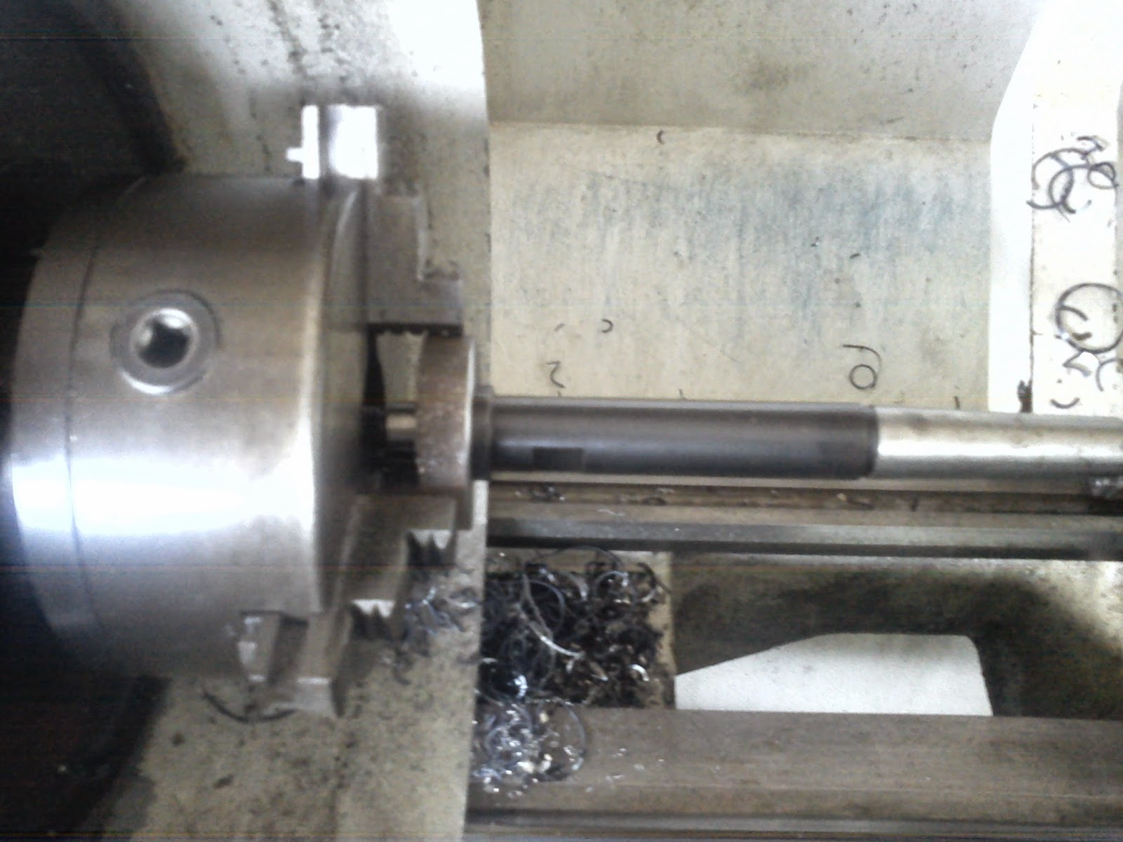
d. Mandrel
2 Turning
a. First turning the face of workpiece until it flat
b. then make hole with twist drill and enlarge by ISO 9 until diameter fit to the mandrel
c. turning the face to other side of workpiece until flat according to gear thickness size.
d. clamp the workpiece to the mandrel an turning outside diameter according to Addendum diameter size
beware if the chip is rolled over the work piece cleane it with chips hook don't clean with your hand or it can be fatal injury.
e. make chamfer to clean the sharp edges.
Making the gear.
1. prepare the tool
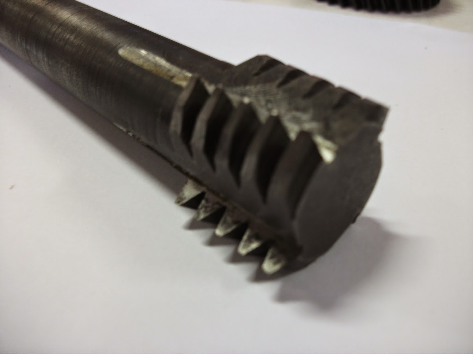
first i prepare tool what i called it semi hobing gear cutting tool
2. Mount dividing head to the table of milling machine and mount the MT3 mandrel to the center hole dividing head, the clam work piece to mandrel
3. Mount the tool to the collet arbor, these arbor is NT40
4. Setting center of tool using dead center of the tailstock.
5. setting zero point off tool to workpiece and cut it with depth of cut every 0.5 mm until 3 mm.
6. then finish the depth to 3.25 mm. you can calculate depth with height of gear formula. for modul 1.5mm it can be height of gear 3.25 mm.
7. with same depth, rotate the crank 20 hole at the sum of hole 30 or 44 hole at 66 sum of hole to make 60T of gear. you can calculate it by dividing equation of dividing head
Nc = i / z
Nc = Rotation of Crank
i = according to dividing head worm ratio = 40
z = number of teeth
8. repeat step no 7 every cutting until 60 teeth
9. after finish the gear unmount it from mandrel an debuur for clean the chip and sharp edge with file.
And now i can connecting X Axis to the dividing head to make a helical gear with change gear


No comments:
Post a Comment